How I made my own apparatus for the double-slit experiment.
Be aware that if you make one of these devices for yourself you must
follow the manufacturer's rules for laser use (unless you use the
pre-laser method involving a pinhole admitting sunlight into a darkened
room, etc.) because you could burn a
portion of your retina by looking into the beam. You are entirely on
your own. I only explain how I made something for my own use.
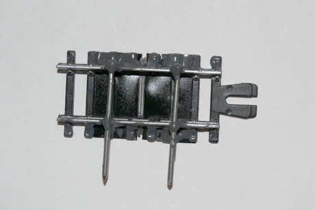
1. I got a plastic railway track section from a toy store. I could have
made a similar frame from chopsticks with a square cross-section.
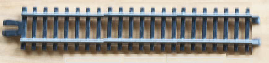
I found these little track segments in a "dollar store" toy section. I
got a package of several of these plastic units (shown here at about
life size) for one dollar. I was a little surprised to discover how
sturdy they are.
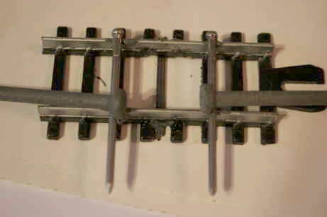
2. I cut the plastic track down to a suitable length.
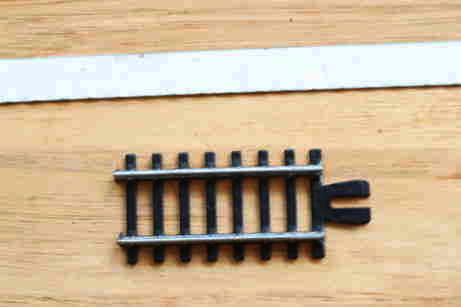
Only a couple inches of track are needed to make a support for the
double slits, so I cut off a short piece using a fine-toothed hack saw
blade (white painted metal strip shown near the top).
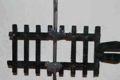
3. I made a rough opening in which to place the bars that will form the
two slits.
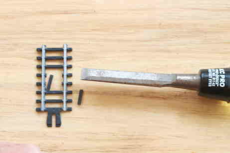
I used a steady heavy pressure on the handle of a wood chisel of
appropriate width, which allowed me to cut out
a couple of the "ties," but the cuts were not flush
with the rails.
4. I smoothed the edges of the opening.
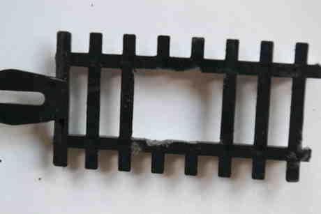
It is difficult to find tools small enough to do a perfect job. I used
the same hacksaw blade mentioned above to saw out the little left-over
parts of the "ties" that I cut out with the chisel. A small file would
have done a neater job.
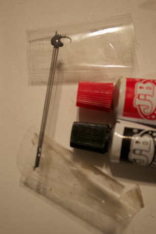
5. i arranged three pieces of automatic pencil lead, and then taped one
end of the
three pieces and fastened them with JB WeldⓇ. In the past I have used
faster-drying adhesives with success.
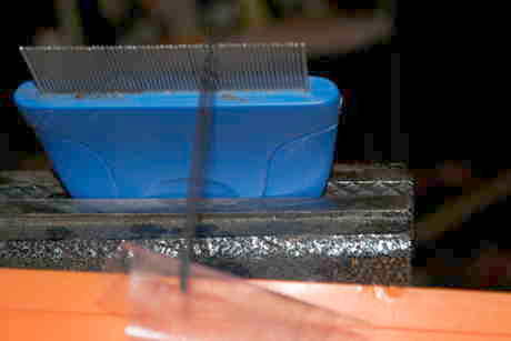
Getting three automatic pencil leads lined up properly is not easy. All
three must be parallel and they need to have equal spaces between them.
I tried various ways and ended up pushing the ends of the three leads
between adjacent teeth of a comb designed to remove fleas from the
coats of cats. I had to clamp the blue plastic handle of that comb in a
vice to make it hold still for me. Then I held the other ends together
and stuck them to some transparent packing tape. (I had to roll the
tape into a cylinder and put one finger inside in order to be able to
control the pencil leads and the tape with two hands.) Once I had them
in approximately the correct position, I mixed a little JB
Weld
adhesive
and dabbed some onto the ends that were stuck to the tape. JB Weld
takes about four hours to dry, but it is extremely strong and I could
still move things around while it was drying. Other products dry faster
and most should be adequately strong, but JB Weld was what I had at hand
6. I put a dab of glue on the taped end.
It's difficult to see the grey glue on the ends of the leads where they
are held by the tape, but it's there. I made sure to let it
dry
thoroughly before going on to the next step.
7. I taped the other end of the pencil leads and then put a dab of glue
on them.
I next held the leads near the flea comb end and stuck them down to
another cylinder made of transparent packing tape. Following that, I
put glue on that end. At this time I made a few adjustments
necessary to get the spacing between the pieces of pencil lead right. I
could have used slips of
paper to force them farther apart if it had been necessary,
but
this time I got lucky. (The
slits in the device I made are approximately 0.01 inch apart.) Then to
both
ends I applied a fairly large drop of adhesive to stabilize the pieces
of lead in the correct relationship to each other. Because JB Weld
dries relatively slowly I took a look at my project from time to time
just to make sure that nothing had slipped out of place. I wanted to
have a very stable bond once everything was lined up properly, a bond
that would not pop loose somehow and spoil all my efforts.
8. I positioned the leads on the track track and and then put a dab
glue on one end.
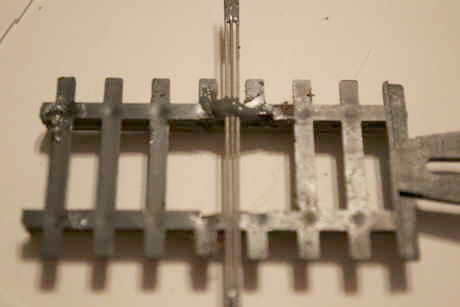
I found the part of the three-lead unit that had the best spacing
characteristics, and fixed the unit to one of the horizontal members
with
a dab of
adhesive so that the best part would be within the tracks.
9. I straightened the three-lead units and dabbed glue on second end.
I made my best attempt to line up the three-lead component so that it
was perpendicular to the plastic "tracks." Only then did I put a dab of
adhesive down to join
the leads to the second "track."
10. I glued both juncture points securely to the track once the
position was idealized.
I appplied plenty of adhesive once the components were positioned
correctly
because I was getting ready to clip the excess lengths of pencil lead,
and I did not want to break anything except the excess lengths. When
the bonds were solid I grasped the pencil leads with a forceps just
inside
inside the part that I wanted to remove. I held the forceps tightly and
snapped
off the unwanted end. then I repeated this operation on the other side.
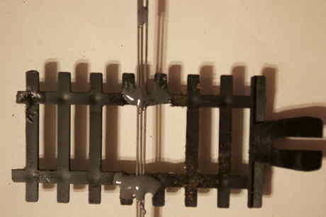
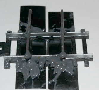
11. I positioned small nails to act as vertical mounting supports, and
I weighed them
down with larger nails, and dabbed the small nails with adhesive at
their
junctures with the tracks.
I first turned the plastic "railway track" over. I glued two small
nails (about
twice as long as the track is wide) to the
edges of the "window" in which the pencil leads had been glued. They
looked like they might slip around so I weighed them
them down with much heavier nails to keep them in
the proper position while the adhesive was hardening. I tried to make
very sure that the
vertical supports were mounted at 90° to the track before the
glue set. Once I had everything positioned correctly I added
enough adhesive to create a very strong bond.
12. I turned the apparatus over again and taped up the open
spaces in
the "window."
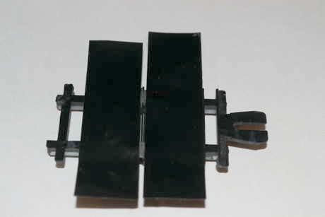
It is important to cover the outside pencil leads to their middle
points, but not any further. So I slowly slid the strips of tape from
the
outside toward the inside, and then let them adhere to the tracks when
they had just closed the gaps between the outside edges of the leads
and the large empty spaces in the frame.
13. I turned the whole thing over again and glued this new
tape to the
back side of the tracks, just to be sure it would not come off.
Electrician's tape has good adhesive qualities, providing that the
adhesive surface is not contaminated with powder, oil, etc. However,
having gone to a fair bit of trouble to line eveything up I did not
want the tapes to fall off, so I put
some JB Weld on the back side to try to ensure that the tape
will stay permanently
joined to the rest of this apparatus. It was difficult to get
the
adhesive to go on smoothly, but I was much more concerned to bridge the
gaps between the outside nubs of the "ties" so that the tape would be
attached in an unbroken line all along the parts outside rails.
14. I trimmed off the excess tape and adhesive.
I used ordinary scissors to cut through the tape and the
thick layer of adhesive, leaving the edges relatively even.
15. I made my own arrangements to secure a laser and learn how to use
it safely. All laser devices carry warnings not to look into the beam.
The
reason is that the laser light can burn a hole in your eye, sort of the
way that a magnifying glass can direct the light of the sun onto
something and burn it. I believe in being cautious, so I sometimes use
a pair of special safety glasses designed for the specific frequency of
the laser light. Because the double-slit part of the apparatus I made
is all black I felt it was relatively safe compared to an earlier
version that used shiny brads. Because they were reflective, a beam
from the laser might get bounced directly into my eyes. I
did not want to take chances. I knew that I should not view any beams
coming from the laser itself -- even through the double-slit apparatus.
16.
Once I had turned on and aimed the laser, I saw the interference (shown
in the photo below) projected on a white screen a few feet away.

I viewed this interference pattern on a white matte surface to avoid
the possibility of direct reflections from the laser. (See Laser Safety
on Wikipedia.) Lasers come in different strengths. Anybody who uses a
laser
should
follow the warnings on the laser. On my laser it says: "Laser light is
harmful to eyes! Do not look directly into beam!"
Anyone who wants to make experiments using lasers is entirely
responsibility for their own safety. The author of this page takes no
responsibility for the acts of others, and offers no claim of safety.
To the contrary,
Always take
all due precautions when using lasers. Laser light is harmful to eyes!
Do not look directly into a laser beam!


Number of guests: